Erasing firmware password
On some occasions, like myself, you may be forgetful, and forget what you set your bootup ("firmware") password to. Unfortunately for you, if you boot in recovery mode using Command-R, it still wants you to remember your original password to erase the old one.
The proper way to do this is to take the computer to Apple with proof of purchase and they will do it for you. However, if like me you only buy their much older machines due to their upgradability, you may find that you don't have proof that you bought it in an apple store, e.g. second hand, or you lost the proof years ago. So, how do you reset it? The answer unfortunately, is with great difficulty. This blog page tells you how.
Please note that I disclaim responsibility for the below - if you blow up your Macbook it's your fault. Do not follow these instructions.
I followed these:
https://blog.wzhang.me/2017/10/29/removing-mac-firmware-password-without-going-to-apple.html
However, they are not 100% clear on all points. Hence, the below clarifies what he means. The below are not instructions intended for you to follow.
1. Software install
Software installreboot while plugged in to make sure the Pi creates the /dev/ devices to talk to the chip.sudo su
apt-get install flashrom
You should see a device called spidev inside /dev/, like so:modprobe spi_bcm2835
ls -al /dev/spidev*
if you see two devices, your chip is probably the newer one, e.g. spidev0.1
2. The electronics components required:
Each resistor must be 150 ohms, not all of them in sum. Total resistance must be 150 x 4 = 600 ohms. The capacitor is 47 uF (microfarads) but can be higher, e.g. 100 uF. You also need male/female wires to connect the Pi to the breadboard and you need male/male wires to connect the breadboard to the clamp.
3. Which wire to join to which.
The diagram that Zhang provides is not clear, this diagram is clearer.
The lines to plug the wires in are as follows:
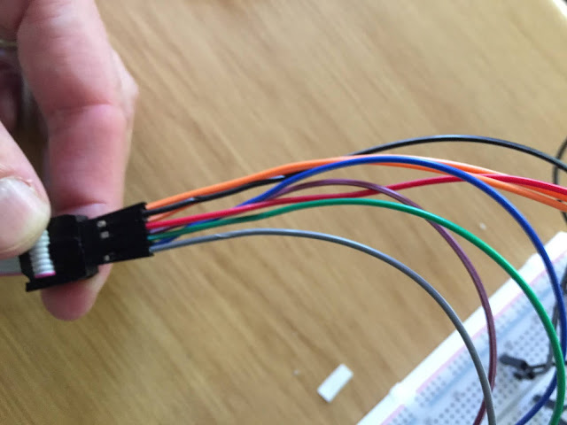
a. Grey - to pin 1 on the clamp. To pin 24 on the Raspberry Pi.b. Green - to pin 2 on the clamp. To pin 21 on the Raspberry Pi.
c. Red - to pins 7, 8 and 3 on the clamp. To pin 17 on the Pi. Obviously, pins 7 and 8 on the clamp go first to the "breadboard" as shown above, then through the capacitor, then to the red input line from pin 17 (power source).
d. Black - to pin 4 on the clamp. To pin 25 on the Pi.
e. Blue - to pin 5 on the clamp. To pin 19 on the Pi.
f. Purple - to pin 6 on the clamp. To pin 23 on the Pi.
To explain the above: pins 1, 2, 5 and 6 are data lines of sorts. Pins 3, 7 and 8 are power lines (positive). Pin 4 is negative/ground.
The pins are numbered starting on the opposite side of the Pi's ethernet/USB plug sockets, so pin 1 and 2 are the two furthest pins. If you face the Pi away from you with the USB towards you, pin 1 is the first on the left and pin 2 is the first on the right. Even pins on the right, odd pins on the left.
The clamp pin holes are numbered top to bottom in a backwards-C shape (clockwise):
1 2 3 4
8 7 6 5
Ignore the pencil diagram a the bottom, it is wrong.
if the square end of the clamp cable is pointing towards you. Take the red-marked cable going into the clamp as 1, and go from there clockwise.
The above image may be incorrect, if in doubt, swap 7,8 and 5,6.
The final setup looks like this: Orange are pins 7,8 in series with the capacitor. Also note the long leg of the capacitor / stripe is the plus side which must be opposite the red line / on the red line.
4. Verify you have the right wiring
You can verify each pinout from the Raspberry pi using an LED, to make sure the lines are active and the circuit has electricity.Edit a new python script, called, for example, blink_led.py, and put the following code in it. If you change the value of "mypin" below it will allow you to send a signal down the pins. Note you can't test 17, 25 and 6 as those are live lines which always have power. In the below code you can omit the comments (#). Note that in python the indents with tab are important. To exit this code after running it, hit control-C. You'd run it with
python blink_led.py
import RPi.GPIO as GPIO # Import Raspberry Pi GPIO library
from time import sleep # Import the sleep function from the time module
mypin=23 # cant use 17, 25, 6 it is reserved
print "using pin"+str(mypin)
GPIO.setwarnings(False) # Ignore warning for now
GPIO.setmode(GPIO.BOARD) # Use physical pin numbering
GPIO.setup(mypin, GPIO.OUT, initial=GPIO.LOW) # Set pin to be an output pin and set initial value to low (off)
while True: # Run forever
GPIO.output(mypin, GPIO.HIGH) # Turn on
sleep(1) # Sleep for 1 second
GPIO.output(mypin, GPIO.LOW) # Turn off
sleep(1) # Sleep for 1 second
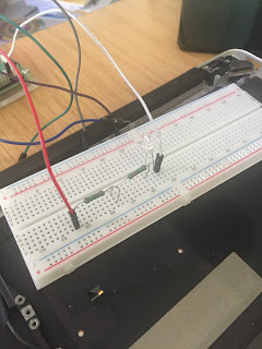
But be sure to put about two resistors inline with the LED or it will blow. (300 ohms at least). The following photo shows you how to wire the breadboard with one LED to test a single line. Move the red line from one pin to the next to test each one to make sure you are getting power out of it.
5. Verify the clamp is seated properly
When you clip the clip onto the motherboard chip, you must make 100% sure it is seated properly first. The chip is the one with 8 legs, quite large (not microscopic). On a 15" macbook it is UNDER the motherboard (hidden, you have to unscrew the whole board). On a 13" macbook it is visible by just removing the back cover. ALWAYS make sure the battery is removed/unplugged first.
Clamp like so:
Once you are sure it is all perfect, first test if the chip is there with
flashrom -V -p linux_spi:dev=/dev/spidev0.0,spispeed=1000
This will give you your chip model name.

To get a copy of the chip, try:
the entry "spispeed" tells the Pi how fast to read the chip.flashrom -r read1.bin -c "MX25L6506E" -V -p linux_spi:dev=/dev/spidev0.0,spispeed=8000
If you find that later on the md5sums don't match, try go down to spispeed=1000.
Note that the item "N25Q064..3E" is the chip model. I found that my chip was in fact "MX25L6406E/MX25L6408E".
flashrom -r read1.bin -c "MX25L6506E" -V -p linux_spi:dev=/dev/spidev0.0,spispeed=8000
flashrom -r read2.bin -c "MX25L6506E" -V -p linux_spi:dev=/dev/spidev0.0,spispeed=8000
You can use
to check the block sizes of all copies you make of the chip, in particular, after you have edited it, you must make sure it is the same size (although the md5sum will differ).ls -al *.bin
In my case, the image of the chip was 8mb in size.
should return the same answer for every original copy of the chip.md5sum *.bin
8. Now do the edit on the image file of the chip:
When you remove the password by editing the hex dump, you can edit it on the Raspberry but use hexedit. There is a graphical app Ghex which doesn't seem to allow copy/paste to work properly or as expected, so you have to learn to use hexedit. Basically, as a clue:
- tab switches you between sides (the "rendered" side of the screen and the raw hexadecimal)
- as you type, it will change both sides of hexedit. You want to be in the "hex" side to type FF (255 in decimal) over the password. The passwords (there are two), commence directly after the string $SVS and end just before a batch of FF FF FFs. You must replace them using the exact same number of FFs, so just hold down F until you reach the FF FF FF part. If there are some 00s inside the password, ignore that, overwrite them with FFs. It should require about 300 FFs to overwrite the first password.
- To search for $SVS, type a forwardslash when you are on the rendered side (not the hex side). There are two instances, and the second one only has about 100 FFs that are needed after it.
- Oh, important because this is one of the things that's not clear: LEAVE the $SVS intact.
- When you exit with control-X it will ask you if you want to save.
Suggest you call it newimage.bin
The picture below is of Ghex, I found it was too hard to use, ironically.
Once you have edited the file, saved it, and verified that it is exactly the same size as the original file, you can erase the chip and copy your edited version in place.
9. To erase the chip: WARNING: MAY TURN YOUR LAPTOP INTO A BRICK.
flashrom -E -V -c "N25Q064..3E" -p linux_spi:dev=/dev/spidev0.0,spispeed=8000
Obviously, if your chipset is not N25... whatever, you must use the right chip identifier name.
10. To copy in the new image of the chip: WARNING: MAY TURN YOUR LAPTOP INTO A BRICK.
flashrom -w newimage.bin -V -c "N25Q064..3E" -p linux_spi:dev=/dev/spidev0.0,spispeed=8000
if it worked, it will look like this: note the "write done" comment at the bottom.
11. If it failed, that is, if your laptop doesn't boot, then copy the original chip image back:
flashrom -w read1.bin -V -c "N25Q064..3E" -p linux_spi:dev=/dev/spidev0.0,spispeed=8000
Here are some more links on EFI/SMC:
https://discussions.apple.com/thread/4855319
https://support.apple.com/en-gb/HT201518#mbp
https://superuser.com/questions/973693/how-to-recover-corrupted-macbook-pro-smc-firmware
https://www.insanelymac.com/forum/topic/299811-readsmc-for-efi-a-tool-to-enter-read-smc-keys-from-efi-shell-on-real-macs/?page=3


